⚡ The Story
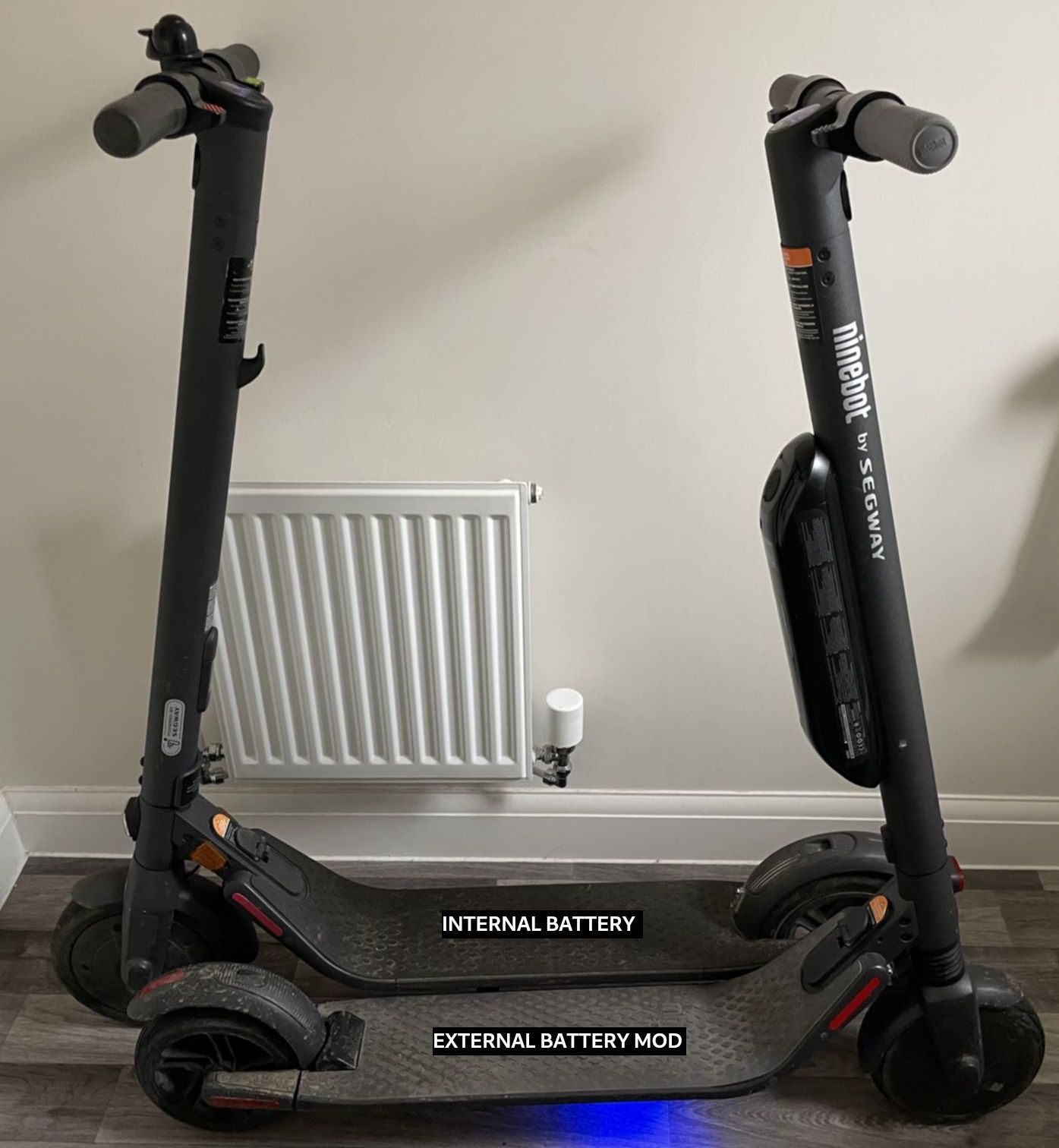
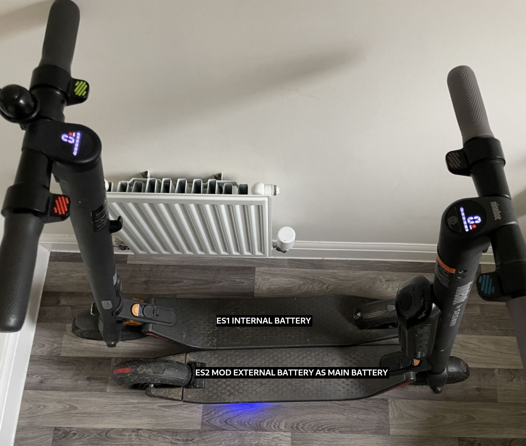
A friend gifted me an ES2 scooter that had stopped working and was about to be
thrown away. The history was unknown, but most components looked fine. The scooter wasn't
charging and was displaying error codes 19 and 21.
After testing the battery, motor controller, display, motor, and sensors, it turned out that
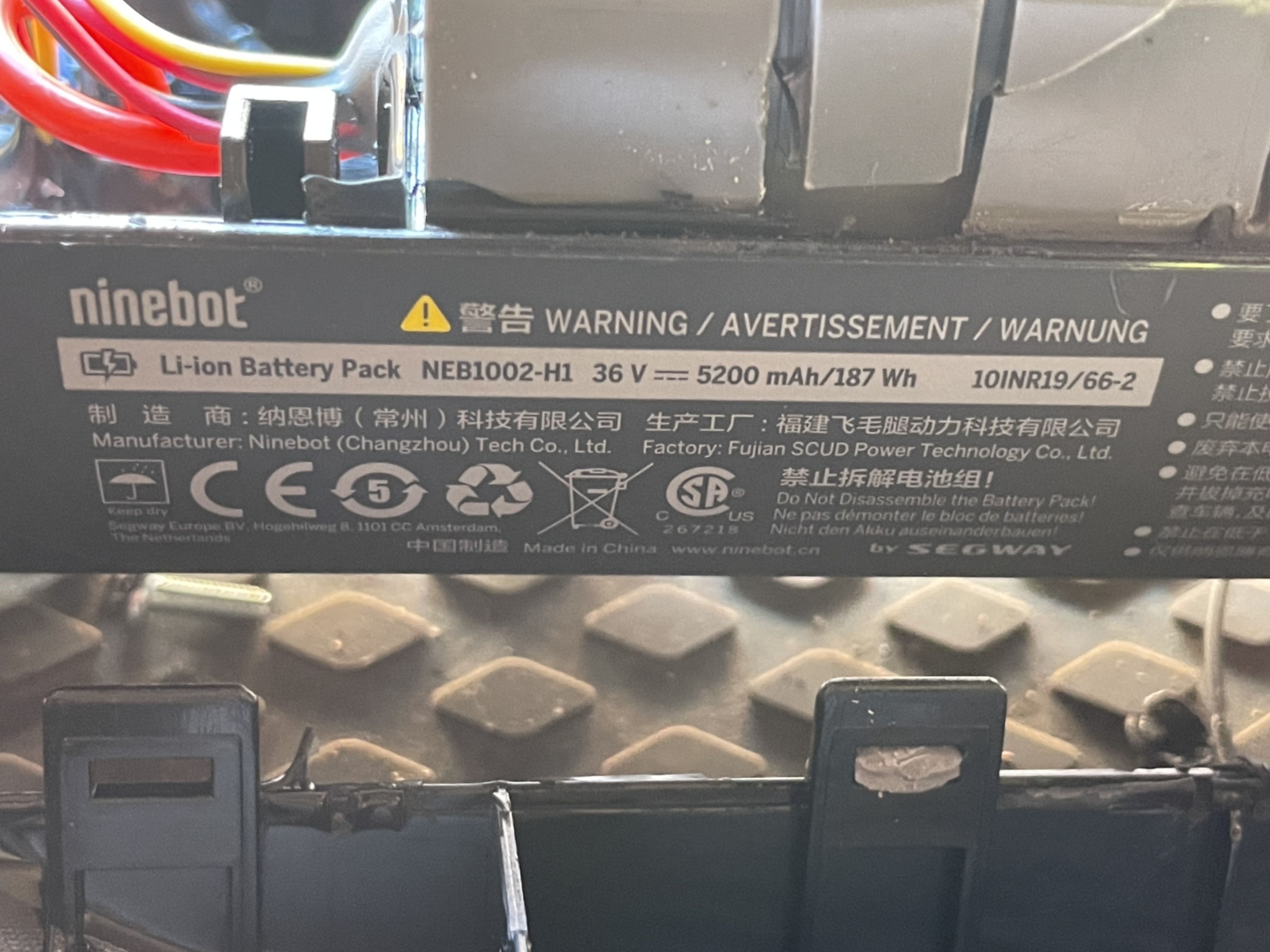
the external battery was fully functional but the internal battery was
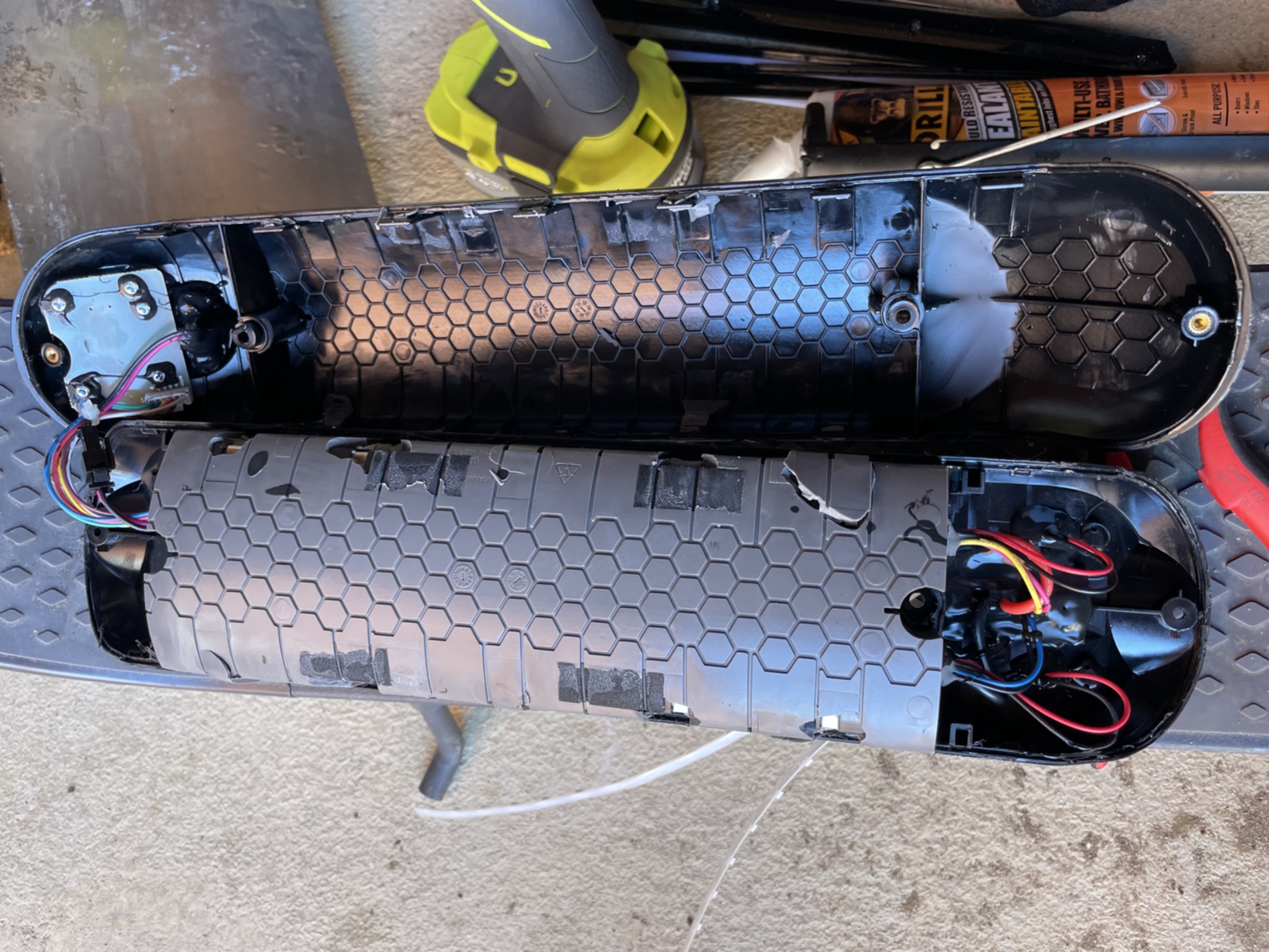
completely dead — no diagnostic LED, no charge held, four damaged cells.
Without spare cells or a spot welder, I couldn't rebuild the main pack. So the question
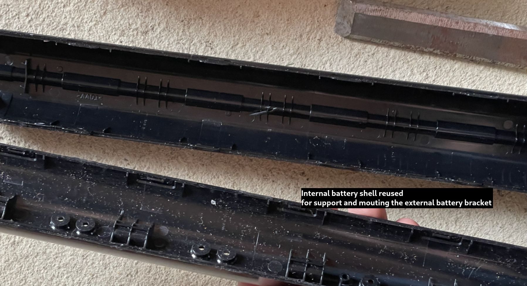
became: can the external battery run the scooter on its own?
Spoiler: yes — and it works great. The mod took an afternoon and the scooter has been riding fine since.
🔍 Key Findings
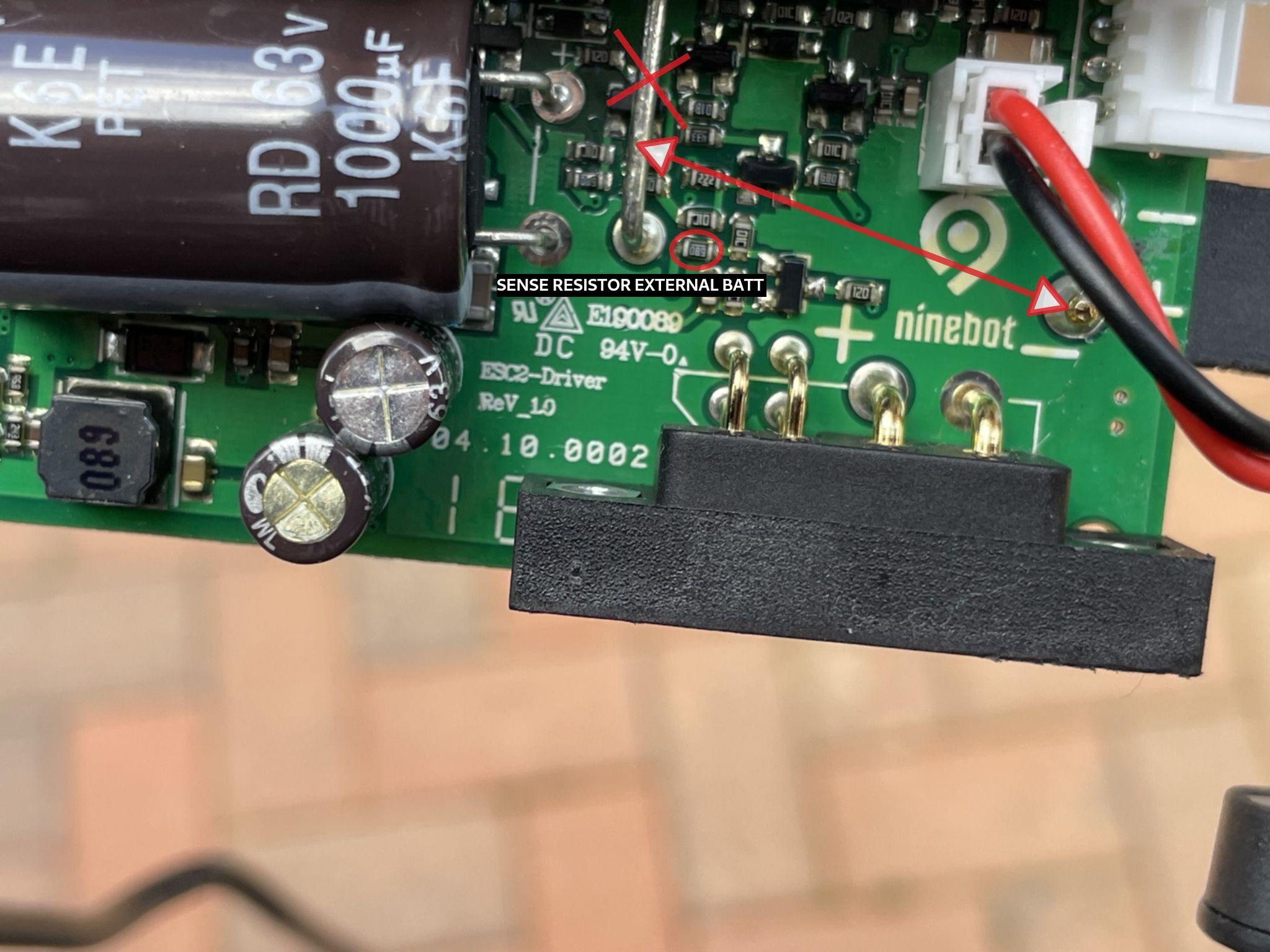
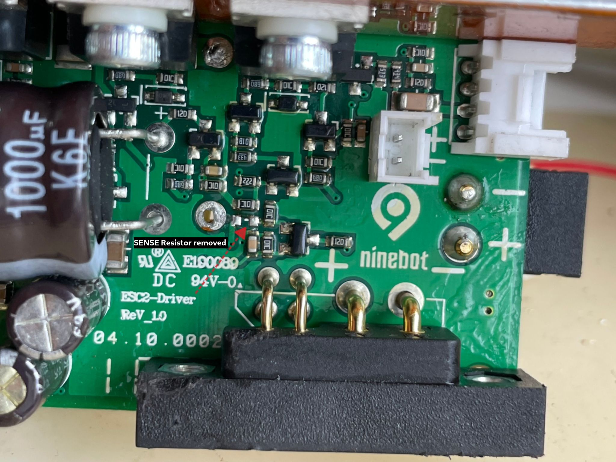
Examining the motor control board revealed a 2 + 4 wire setup — two power
wires and four control wires per battery slot. Critically, the internal and external battery
connectors share a common (−) negative wire and the control lines, leaving
only three truly distinct wires between them:
-
(+) Power wire — unique to each battery slot
-
RX communication wire — unique to each slot
-
TX communication wire — unique to each slot
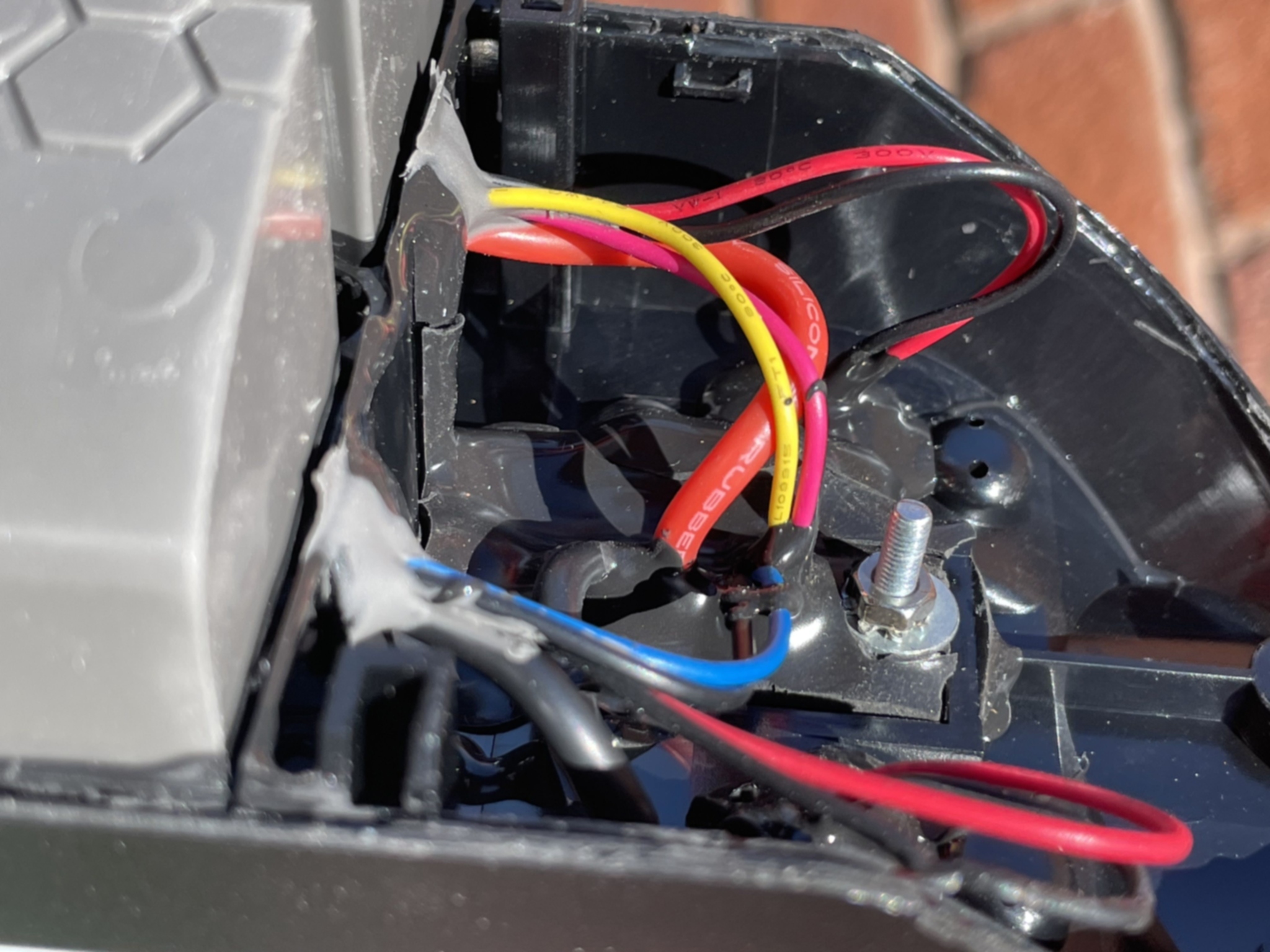
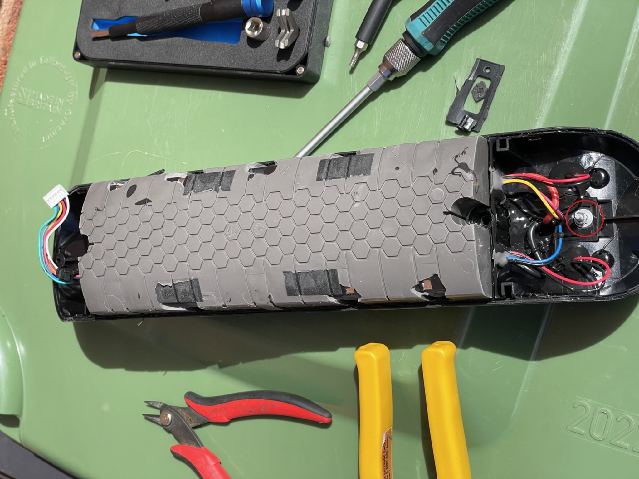
Using detailed MCU pin-out references
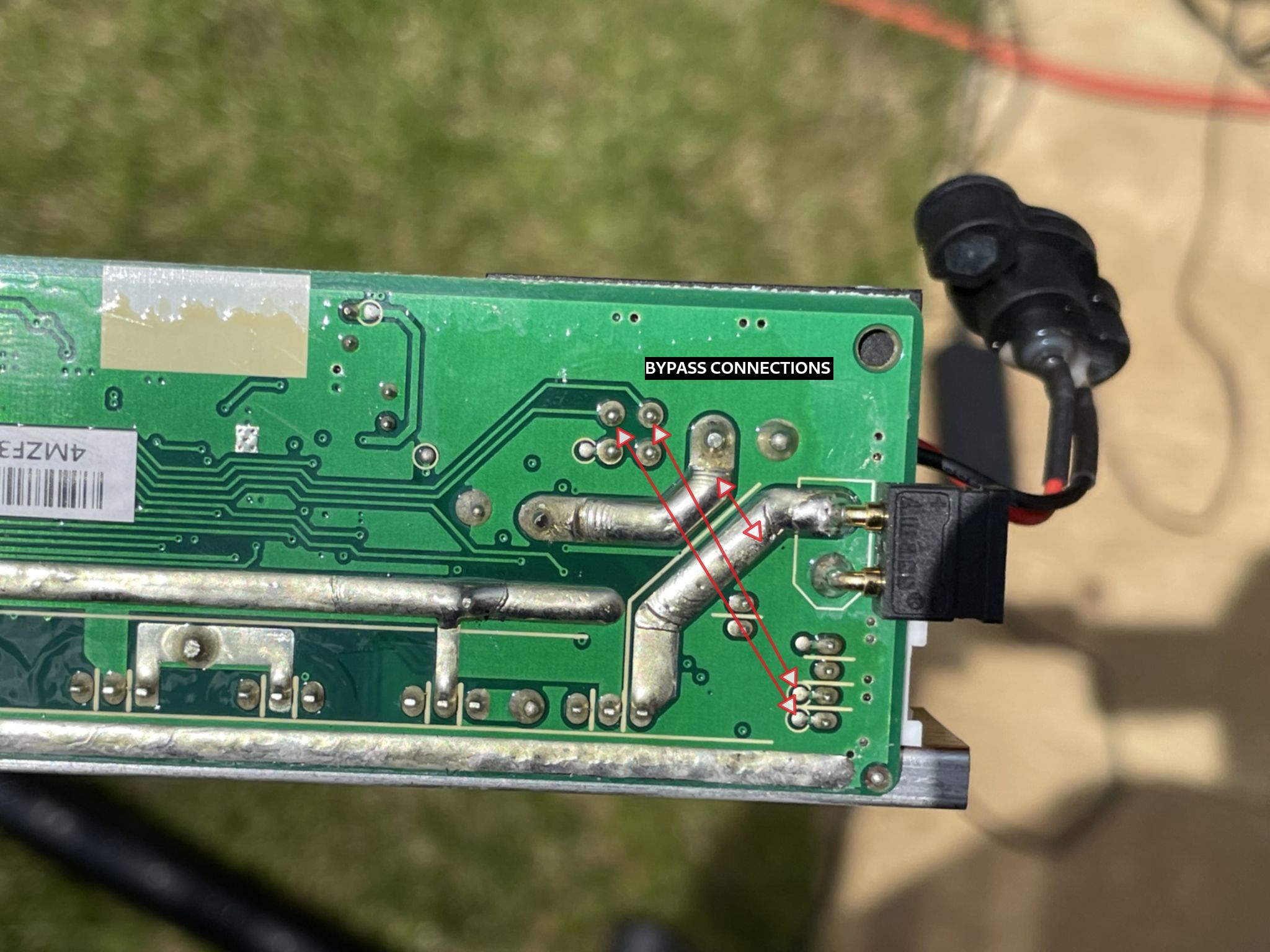
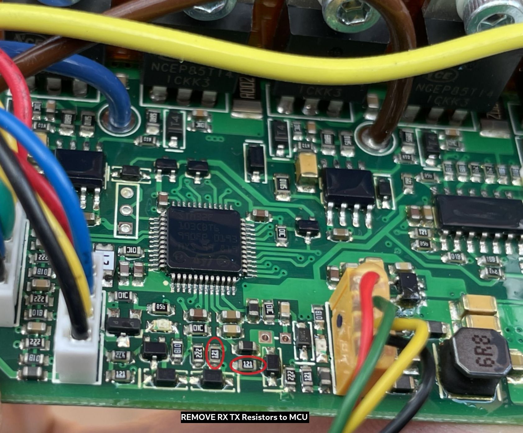
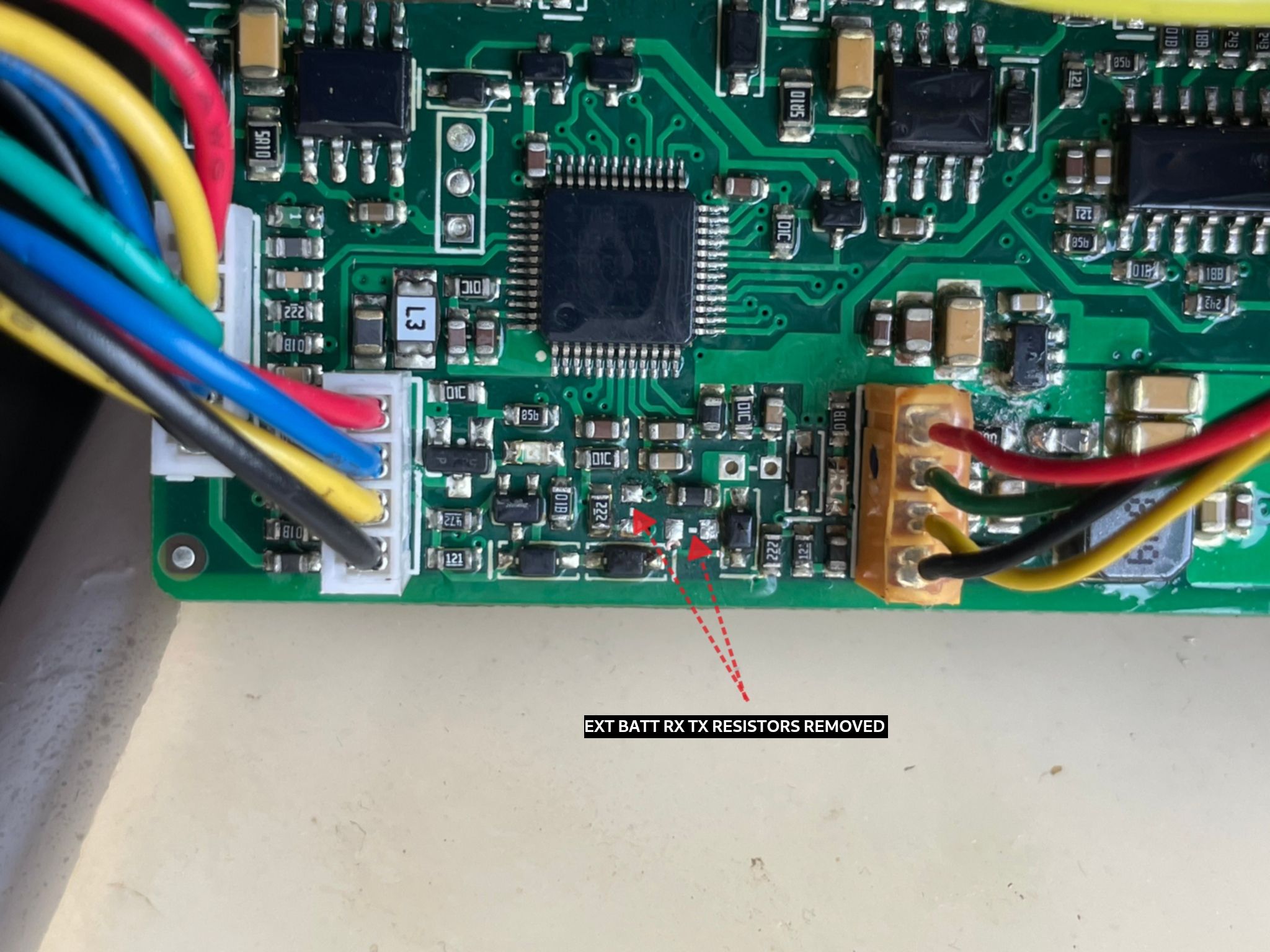
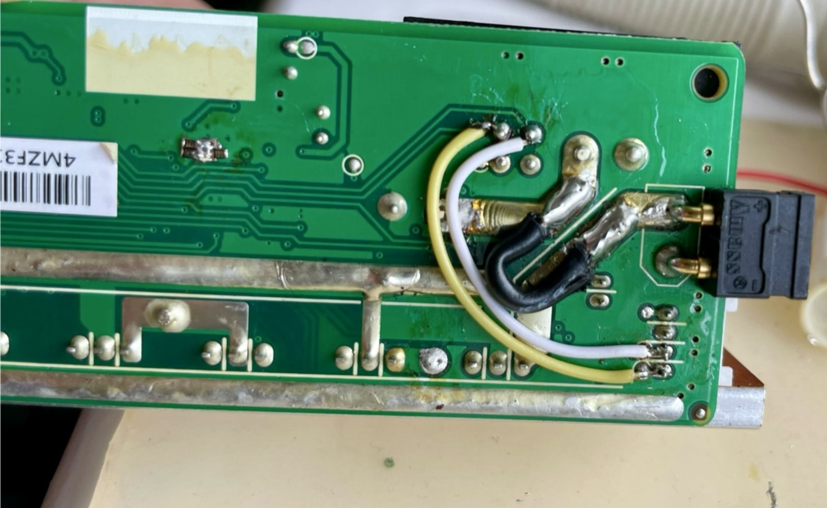
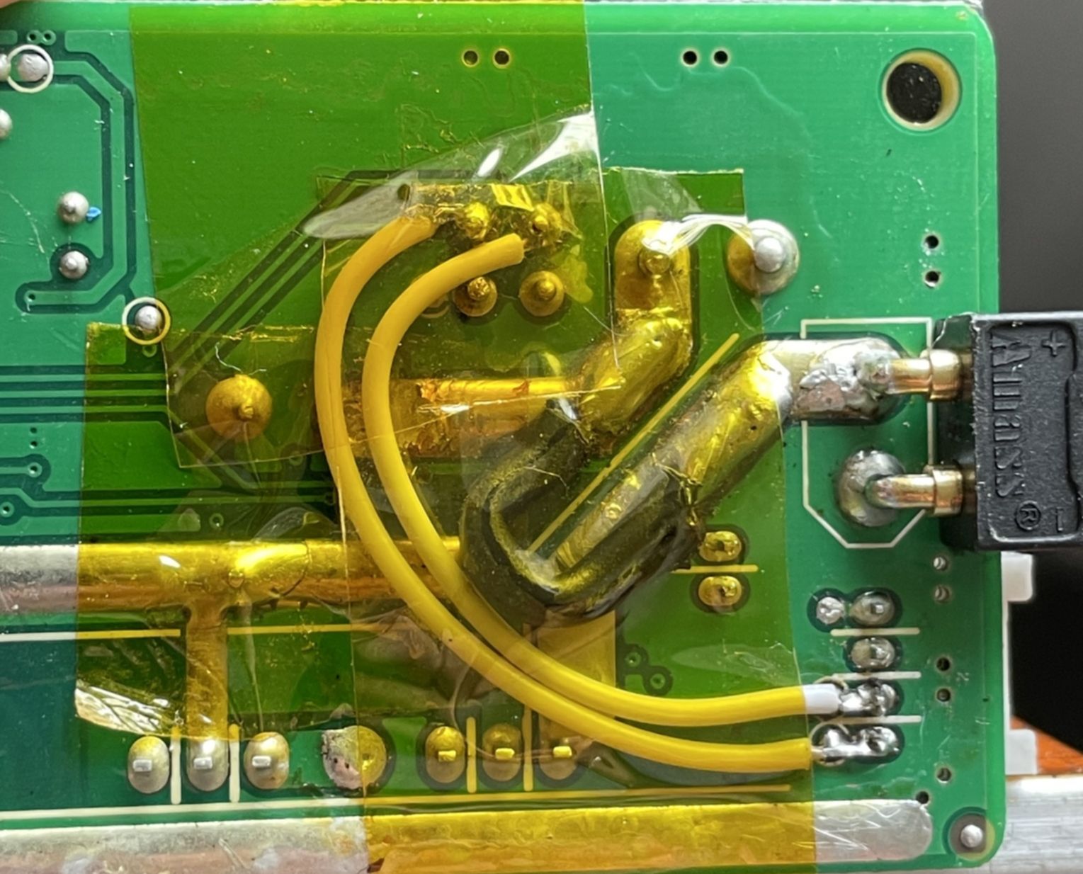
and some trial and error, I figured out how to reroute the external battery's wires to the
internal battery position and disable the external battery presence detection.
🔌 Connector Fix
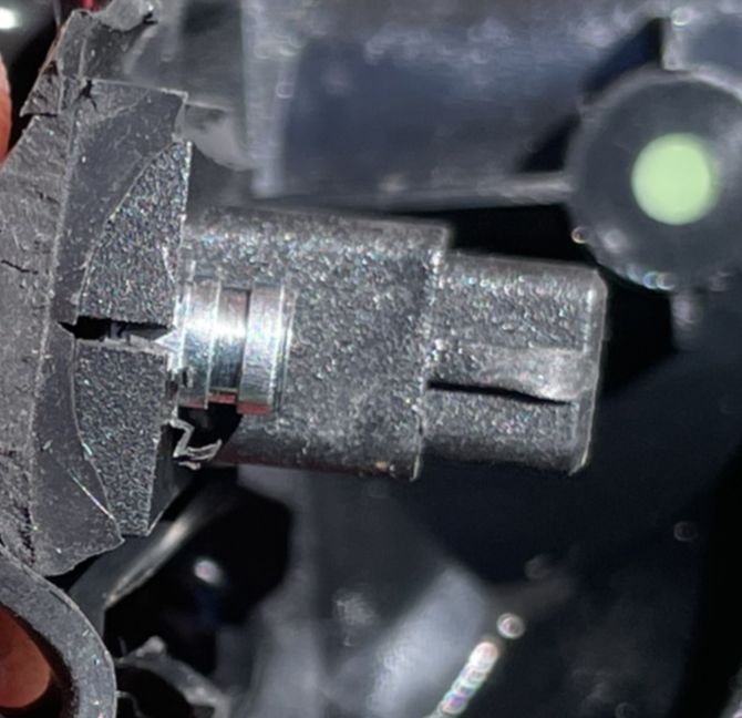
After a successful test ride, error code 21 came back. The culprit was a two-part connector
issue: the internal connector on the motor controller needed a slight physical adjustment, and
the female connector on the external battery had been damaged by an old impact
— probably the reason the scooter was discarded in the first place.
The fix required carefully re-engineering the female connector so it made solid contact. Once
done, error 21 disappeared and the scooter has been reliable since.
Before
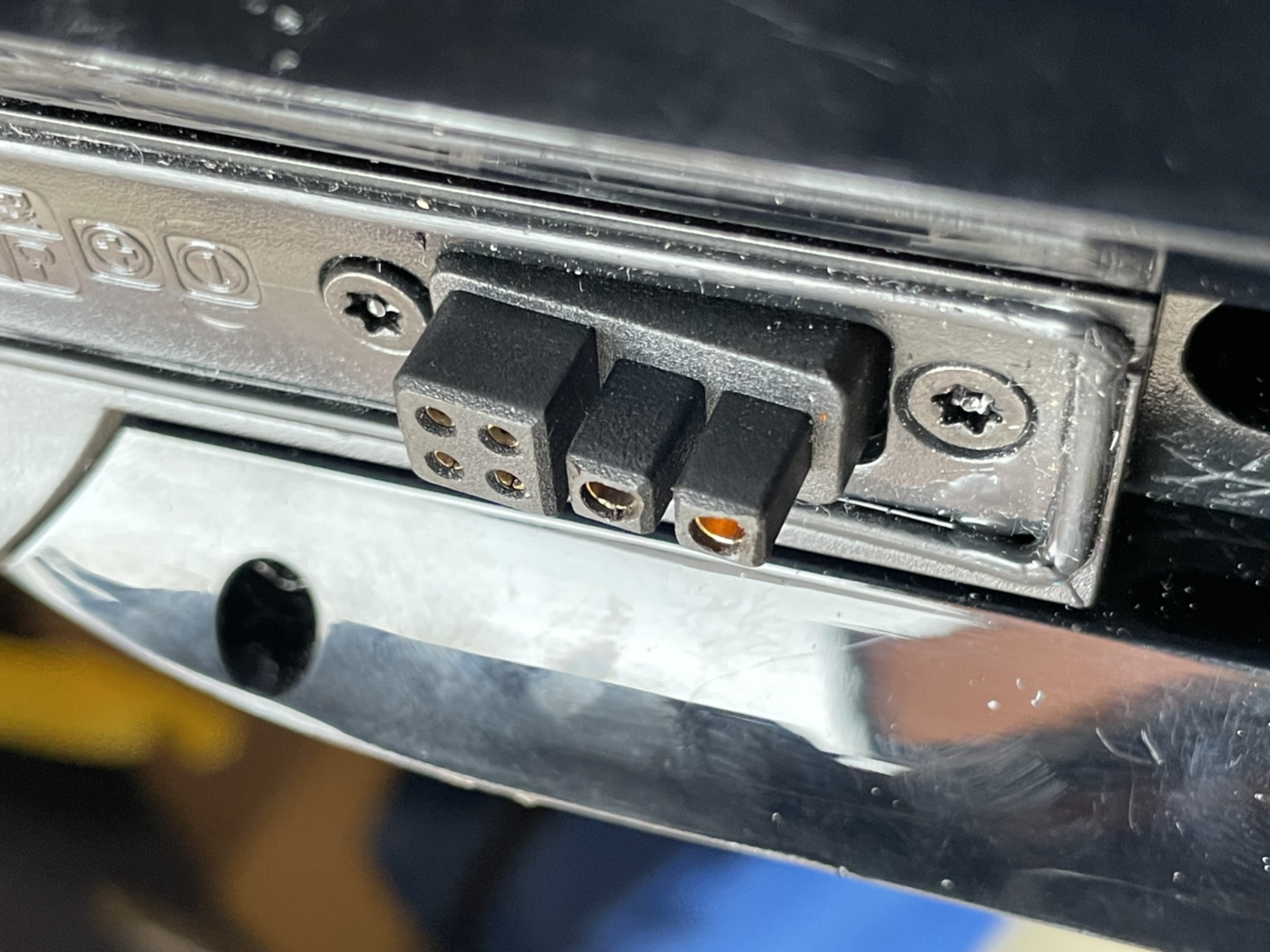
Damaged female connector — bent pins causing intermittent contact
After
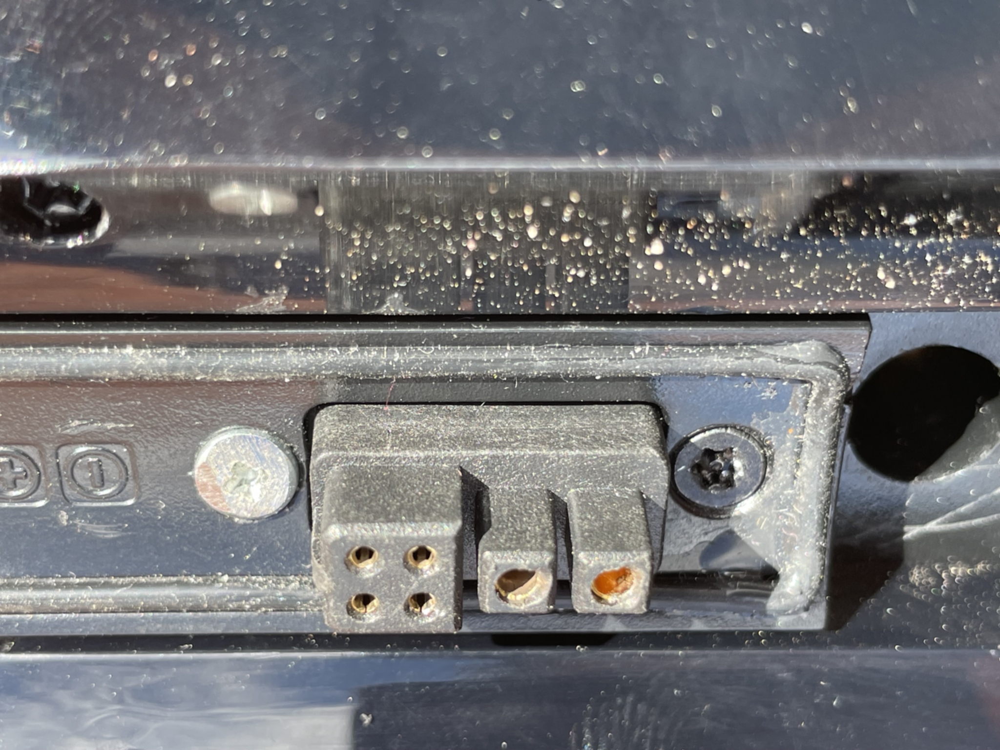
Re-engineered connector — solid contact, no more error 21
Before
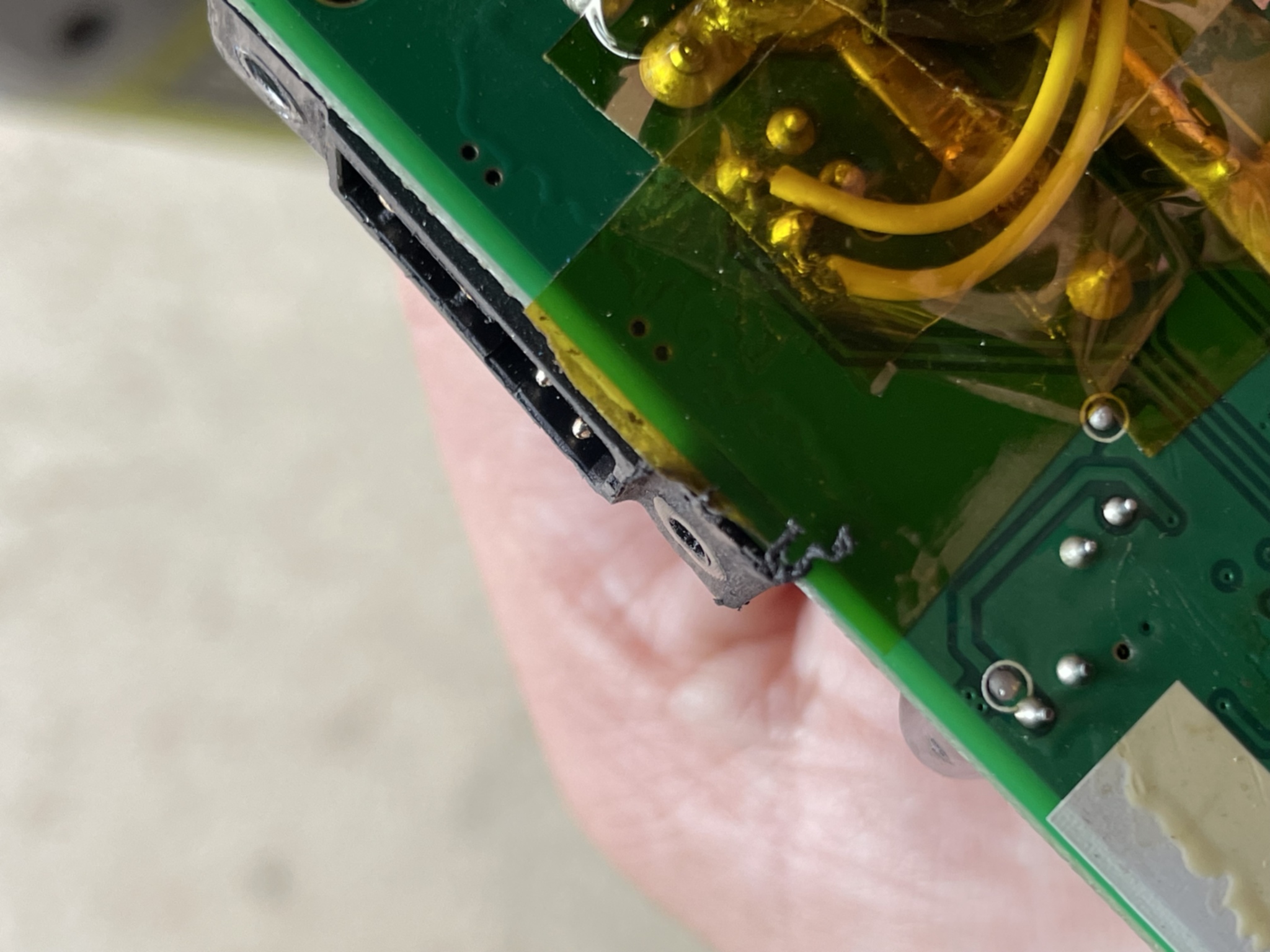
Internal connector on the motor controller, before minor adjustment
After
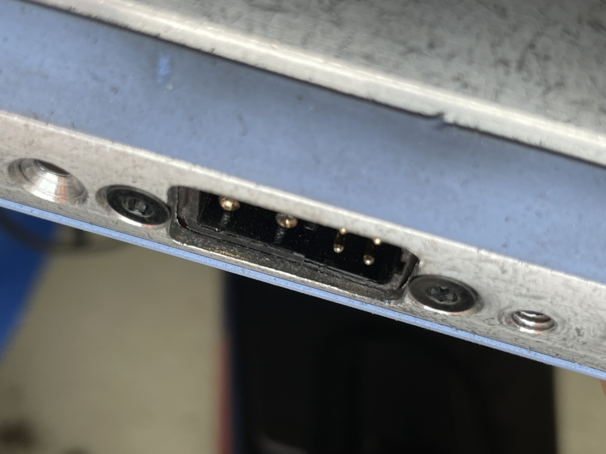
Adjusted to ensure a positive seat for the external battery plug